Under construction
Author: An Do
Introduction: The goal of this tutorial is to provide basic information on how data from a bioamplifier, or array of bioamplifiers can be acquired by an Arduino microcontroller. If you are not yet familiar with the Arduino microcontroller, you can learn about it at the Arduino Official Website.
The concept of acquiring raw signal from a bioamplifier is fairly simple, but a few concepts should be kept in mind:
- Nyquist rate: the sampling rate of the on board analog-to-digital converter (ADC) in Arduino must be capable of properly acquiring the signal of interest. Arduino must be able acquire with at least twice the bandwidth of the signal of interest. For example, since EEG’s bandwidth typically exists in the 0.1-35 Hz band, Arduino must be capable of acquiring at a rate of 70 Hz for a single channel. This becomes more complicated if more channels are involved. Note that the various channels on the Arduino are multiplexed, and so this must also be considered.
- Signal resolution: Most Arduino boards have a 10-bit ADC, which is typically adequate for most biological signals.
- DC Supply: The Arduino, like many other controllers, is designed to operate in the 0-5V range. The output of your amplifier should appropriately bias the signal so that it fits within this range. More specifically, if you use a dual-supply amplifier with the signal centered at 0V, all of the negative voltages will not be recorded by Arduino, and hence you will only get part of your signal.
- Limited processing power: Considering both physical limitations and limited processing capacity, the Arduino has an upper limit as to the number of signals it can acquire properly. Outside of the multiplexing considerations, one must also consider the processing capacity that is required to transmit the acquired data to an external computer, or to store it. An alternative may be to perform analysis within the Arduino controller, but this too may be limited by the processing capacity. Benchmarking and optimization will be key.
Example 1 – Simple, one channel acquisition.
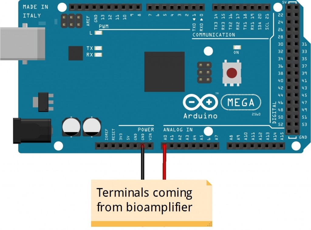
In this example, we will acquire a single channel of EEG through an Arduino. It will be assumed that the output from your bioamplifier is properly biased and calibrated to have a dynamic range of 0-5V, and that a basic connection is established as shown below:
The basic code to continuously acquire samples from a single channel (in this case, channel A0 from the Arduino) is as follows:
|
void setup() { } void loop() { } |
However, this will acquire the signal as fast as possible, and continuously overwrites the variable channelvalue. It will require additional coding for proper timing for digitization. We will assume that the bandwidth of EEG is 0.1-35 Hz, thereby requiring at a sampling rate of at least 70 Hz. For a signal to be sampled at occur at 70 Hz, each acquire cycle should occur every 14.286 ms. The code will need to add some method of delay. One approach is to simply use the delay as shown below. Note however, that this assumes that the sampling requires only negligible time (in the nanosecond range).
|
void setup() {} void loop() { } |
The above approach however has some drawbacks. First, it is likely neither precise nor accurate enough to assume that the acquisition occurs almost instantaneously. Second, since Arduino is single-threaded, delays basically pause all operations on the Arduino microcontroller. Therefore, a potentially more accurate and precise approach is to utilize a timer. This can account for the time required to acquire data and can allow you to run other (brief) processes during your delay times:
| long interval=14286; long currenttime = 0; void setup() {}
void loop() { while (currenttime – starttime < interval) { } |
Since acquisition typically only requires 10- 20 microseconds to complete, you still have some time to sneak in any other operation for the remainder of the cycle time. The while loop in the code above (used as a timer) allows you to insert additional processes, but keep in mind that you should benchmark your code to make sure that the code you are doing does not exceed the allotted cycle time, otherwise, a number of errors may occur. The above example is just one simple approach to doing this, but is not the only way.
Example 2 – Sampling from multiple channels
Under construction